Formulation
Before application and curing, an anti-friction coating consists of four functional components.
Solid Lubricant (10–30%)
MoS2 (high load/pressure), PTFE (low friction/light load), synthetic graphite (high temp/humidity stability), or h-BN (high dielectric strength/thermal stability).
Binder Matrix (10–30%)
Organic polymers (polyamide-imide, epoxy, phenolic, polyurethane) or inorganic compounds (silicates, phosphates) that anchor solid lubricants to the substrate.
Solvent Carrier (30–70%)
Organic solvents (NMP, MEK, xylene) or water (VOC-compliant systems) used to dissolve the binder and disperse solids for liquid spray, dip-spin, or brush application.
Additives (0–5%)
Specialized elements like corrosion inhibitors, dispersion agents, or catalysts added to enhance shelf life, curing speed, and environmental protection.
.png)
Common Binder Types
In an anti-friction coating (AFC), the binder is the resin matrix that locks solid lubricants, such as MoS2, graphite, or PTFE, to a substrate. Binders are divided into organic types (e.g., polyamide-imide, epoxy, phenolic) for toughness and chemical resistance, and inorganic types (e.g., silicate) for extreme high-heat performance.
| Binder Class |
Curing Profile & Temp |
Max Operating Temp (°C) |
Load Capacity / Wear Life |
Chemical & Corrosion Resistance |
| Polyamide-Imide (PAI) |
Heat cure (200°C / 60 min) |
+260 |
Extreme (>2,000 MPa) |
Strong; solvent & acid resistant. |
| Epoxy Resin |
Heat cure (180°C / 30 min) |
+180 |
Very high |
Strong salt-spray corrosion protection. |
| Alkyd / Acrylic |
Air dry / ambient (20°C / 24 hrs) |
+100 |
Moderate |
Moderate; suitable for touch-up applications. |
| Inorganic Silicate |
Heat cure (300°C to 400°C) |
+450 to +650 |
High (brittle) |
Resistant to radiation & ultra-high vacuum. |
Key Functions of the Binder
Adhesion
Bonds the dry-film lubricating pigments firmly onto metal, plastic, or elastomer surfaces.
Matrix Support
Holds solid lubricant particles in place under pressure and prevents them from flaking off.
Durability
Dictates the chemical, oil, and corrosion resistance of the final cured coating.
Advantages & Disadvantages
| Advantages |
Disadvantages & Limitations |
- Completely dry, clean lubrication; minimal oil migration or dirt/dust buildup.
- Stable performance in ultra-high vacuum (10⁻⁹ Torr) and radiation environments.
- Provides long-term dry lubrication for un-relubricable or enclosed components.
- Combines low friction performance with corrosion barrier protection.
- Reduces oil/grease contamination of adjacent product or optics.
- Thin films fit compact mechanisms.
|
- Non-self-healing: once the physical dry film wears through, substrate wear accelerates.
- Lower heat dissipation capability compared to circulating oil or grease systems.
- Requires strict surface preparation (grit blasting, phosphating, precision baking).
- Requires careful application tolerance control to maintain structural clearances.
- Debris may be generated during run-in and wear.
- Film thickness affects clearances, fits, and thread preload.
|
Anti-Friction Coating (AFC) Application Methodology
The performance, adhesion strength, and wear life of an AFC depend as much on the application process as on the coating's chemical formulation. Because AFCs function as thin structural tribological films, typically 10 µm to 20 µm dry film thickness, application requires a strict multi-stage workflow.
.png)
1. Substrate Surface Preparation (Pre-Treatment)
1.1: Degreasing & Contaminant Removal
Objective: Remove all oils, rust preventatives, greases, and shop dirt.
Methods: Vapor degreasing (using chlorinated or fluorinated solvents), ultrasonic bath cleaning, or aqueous alkaline washing followed by a deionized water rinse and hot-air drying.
1.2: Mechanical Surface Roughing
Objective: Increase real surface area and establish a mechanical anchor profile for the resin binder.
Method: Fine grit-blasting using non-metallic, sharp-edged media such as aluminum oxide (Al2O3) or chilled iron grit (grit size: 120–220 mesh) at 0.2 to 0.4 MPa blast pressure.
1.3: Chemical Pre-Treatment (Conversion Coating)
Chemical conversion layers significantly enhance coating adhesion and provide secondary corrosion resistance underneath the solid lubricant film.
| Substrate Material |
Chemical Conversion Process |
Layer Specification / Weight |
| Carbon Steel / Alloy Steel |
Manganese phosphating or zinc phosphating |
3 to 10 g/m² (fine crystalline structure) |
| Stainless Steel |
Passivation or light sandblasting |
Citric / nitric acid, ASTM A967 |
| Aluminum & Alloys |
Chromate conversion or hard anodizing |
MIL-DTL-5541 or Type III anodize (5–10 µm) |
| Titanium & Alloys |
Fluoride-phosphate conversion / alkaline etch |
AMS 2486 / AMS 2488 |
2. Coating Application Methods
2.1: Pneumatic Spray Application (HVLP)
Best For: Large components, complex geometries, low-to-medium production volumes, and high-precision applications requiring strict thickness control (e.g., engine pistons, aerospace valves).
Process Parameters: Atomization pressure 0.2 to 0.35 MPa; nozzle diameter 0.8 mm to 1.2 mm; fluid diluted with technical-grade solvent (NMP, MEK, xylene); spray distance 15 cm to 25 cm using cross-hatch strokes (horizontal followed by vertical passes) to prevent sags and pinholes.

2.2: Dip-Spin Coating (Centrifugal Bulk Processing)
Best For: High-volume processing of small components (screws, bolts, fasteners, clips, springs, brackets).
Process Sequence: Parts are placed in a perforated metal basket and submerged in an AFC fluid bath. The basket is lifted out of the bath and spun at high speed. Centrifugal force throws excess coating off the parts back into the bath, leaving a uniform, thin coating free of runs or head-fill in threaded regions. The spin direction is often reversed halfway through the cycle to ensure equal distribution.
.gif)
2.3: Dip-Drain / Immersion Coating
Best For: Long cylindrical parts, internal tube diameters, or symmetric rods where spraying can't access internal surfaces.
Process Parameters: The component is submerged in the AFC fluid and withdrawn at a controlled rate. Withdrawal speed determines coating thickness via capillary force balance.
.gif)
2.4: Selective Screen / Pad Printing
Best For: Flat localized contact zones, gaskets, or bearing bushes where masking the rest of the component is cost-prohibitive.
Process: High-viscosity AFC formulations are forced through a patterned silk/steel mesh screen or transferred via a silicone pad directly onto the friction face.
.gif)
Flash-Off & Curing Mechanisms
After application, the wet coating layer must undergo a two-phase thermal transition: solvent evaporation followed by polymer crosslinking.
Flash-Off (Solvent Evaporation)
Before entering high-temperature cure ovens, coated parts must undergo a flash-off period at ambient or slightly elevated temperature (20°C to 80°C) for 10 to 15 minutes. This step allows volatile solvent carriers to evaporate gradually. Skipping flash-off causes trapped solvent to boil during curing, resulting in surface blisters, craters, and pinhole voids.
Curing (Binder Polymerization)
The curing cycle crosslinks the binder resin, permanently bonding the solid lubricant matrix to the pre-treated metal substrate.
Quality Control & Inspection Standards
To verify process stability and performance compliance, cured AFC coatings are subjected to three primary quality inspections.
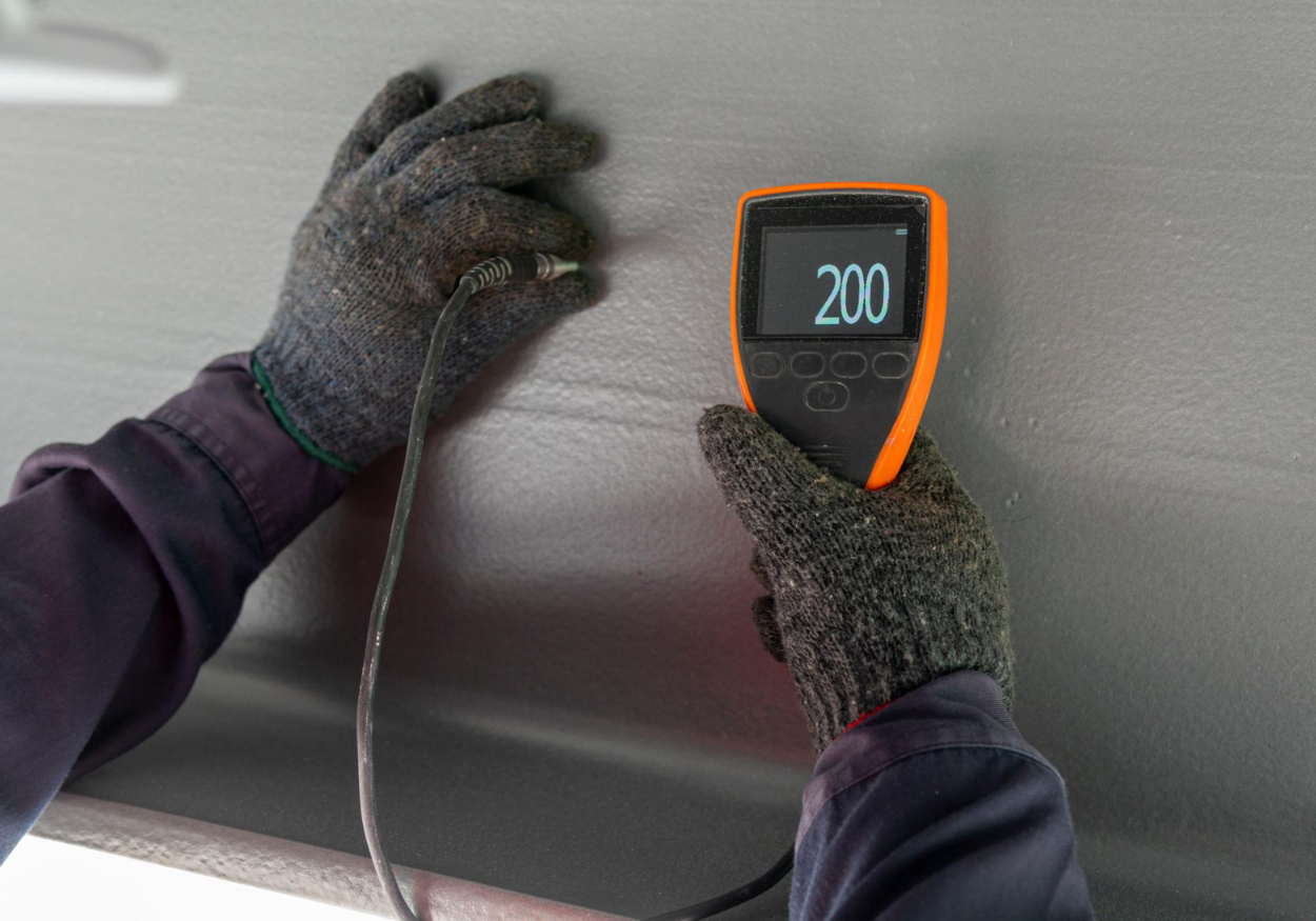
Dry Film Thickness (DFT) Measurement (ISO 2178 / ASTM B499)
Method: Magnetic-induction or eddy-current thickness gauges measure the dry film thickness.
Acceptance Criteria: Typical target range is 10 µm to 20 µm.
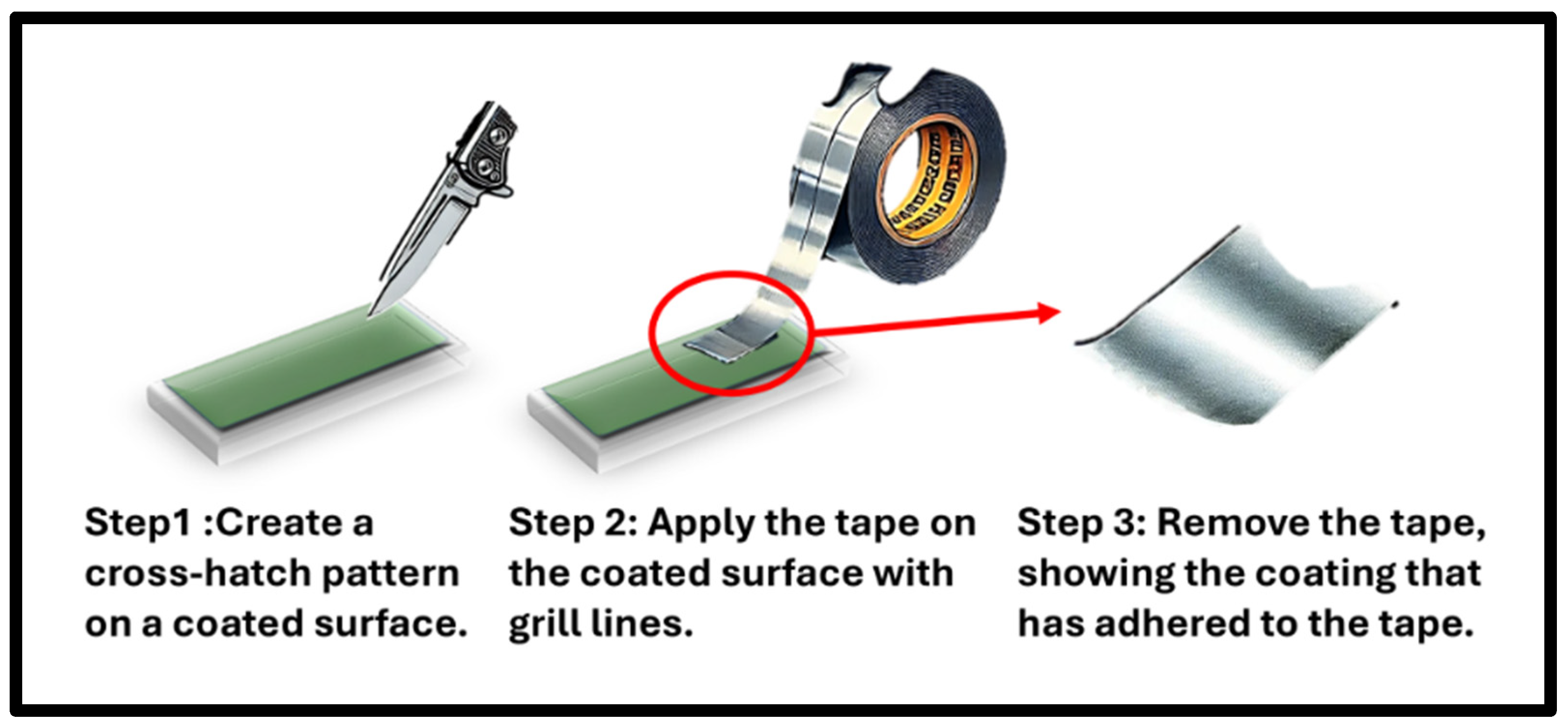
Cross-Hatch Adhesion Tape Test (ASTM D3359 Method B)
Method: A lattice pattern of 6 or 11 cuts is made through the cured film to the substrate using a cross-hatch cutter. Pressure-sensitive tape is applied firmly over the grid and pulled off abruptly at a 180° angle.
Acceptance Criteria: Rating 4B or 5B (zero to under 5% grid flaking at intersections).
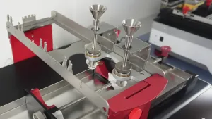
Solvent Rub Test / Cure Verification (ASTM D5402)
Method: A cloth soaked in methyl ethyl ketone (MEK) is rubbed back and forth across the cured coating surface for 50 double rubs under 10 N load.
Acceptance Criteria: No softening, dulling, or transfer of coating material to the cloth, confirming complete resin polymer crosslinking.
Key Sector Applications & Engineering Functions
1. Automotive & Powertrain Engineering
Engine Piston Skirts: Heat-cured MoS2 bound in polyamide-imide (PAI) resin applied to piston skirts reduces cold-start hydrodynamic drag and helps protect against cylinder wall scuffing.
Door Latches, Hinges & Window Regulators: PTFE/epoxy coatings deliver maintenance-free, long-term dry sliding for over 100,000 cycles without transferring oil to passenger clothing or attracting road dust.
Brake Clips & Anti-Squeal Plates: Thermally stable PTFE/epoxy coatings help prevent stick-slip friction and pad drag without trapping abrasive brake dust.
(1).png)
2. Aerospace, Defense & Space Systems
Spacecraft Solar Array Gimbals & Deployment Hinges: Inorganic silicate-bound MoS2 coatings operate reliably in ultra-high vacuum (10⁻⁹ Torr) and radiation environments with minimal volatile organic outgassing.
Jet Engine Lock-Nuts & Fasteners: High-purity MoS2 in a PAI binder helps eliminate thread galling under severe thermal cycling (-55°C to +450°C) and supports predictable breakout torque.
.png)
3. Oil & Gas, Marine & Subsea Equipment
Subsea Gate Valves & Actuator Stems: Fluoropolymer (PTFE) and MoS2 blended with epoxy binders withstand extreme contact pressures (up to roughly 2,500 MPa) while providing extended ASTM B117 salt spray corrosion barrier protection.
Tubular Threaded Connections (OCTG): Dry-film coatings replace traditional heavy metal pipe dope, helping prevent thread galling during high-torque makeup and eliminating marine environment discharge.
.png)
4. Semiconductor Manufacturing & Vacuum Systems
Cleanroom Wafer Transfer Arms & Linear Guides: PAI-bound PTFE dry films provide particle-free sliding motion in Class 1/10 cleanrooms, helping eliminate oil aerosol contamination on silicon wafers.

5. Industrial Machinery, Textiles & Consumer Goods
Textile Yarn Feeders & Printing Equipment: PTFE dry coatings help prevent paper fibers, lint, and dust from adhering to sliding guides, reducing equipment jams.
Solenoid Plungers & Pneumatic Valves: Ultrathin (5 µm to 10 µm) air-drying acrylic/PTFE coatings reduce electrical switching hysteresis and help eliminate stiction.
.png)


