Graphitized Carbon Fiber Paper and Panel Manufacturing
Graphitized carbon fiber papers and plates begin as a thin fiber mat or veil, created through a wet-laying process similar to traditional papermaking. The mat is then impregnated with a thermosetting resin, which serves as a binder, bonding the fibers and providing strength and the desired thickness. Depending on the required thickness, multiple layers of the veil are bonded together and undergo thermal pressing. The material is then carbonized, converting the resin into carbon. Finally, the carbonized product undergoes graphitization at temperatures ≥ 1600 °C.
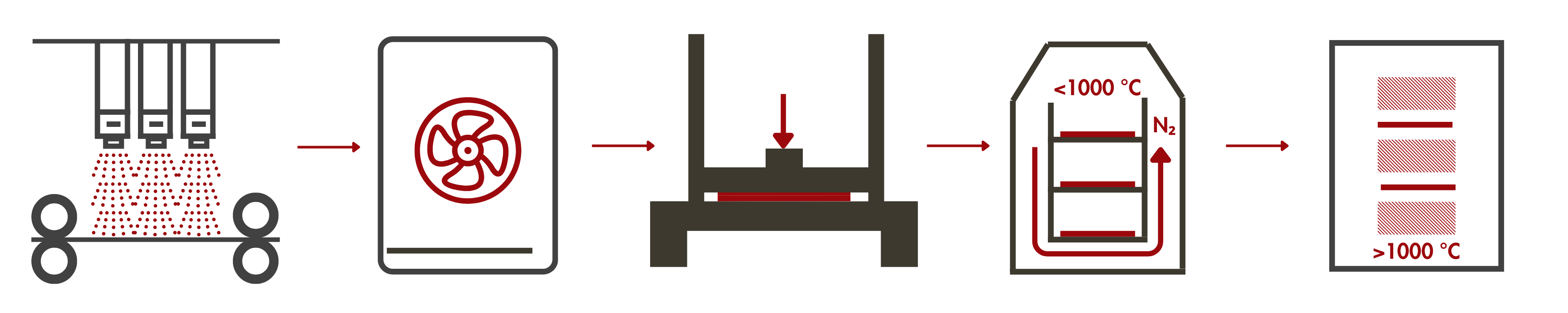
For products requiring additional microporous layers (MPL) and PTFE coating, the graphitized part is fed into a coating machine, where it is coated with the MPL or PTFE dispersion. After coating, the material is dried in an oven to evaporate the solvent.
Read more about the LINQCELL Graphitized Carbon Fiber Paper and Plate Manufacturing Process.
Hydrophobization (PTFE Treatment) in Graphitized Carbon Fiber Papers and Panels
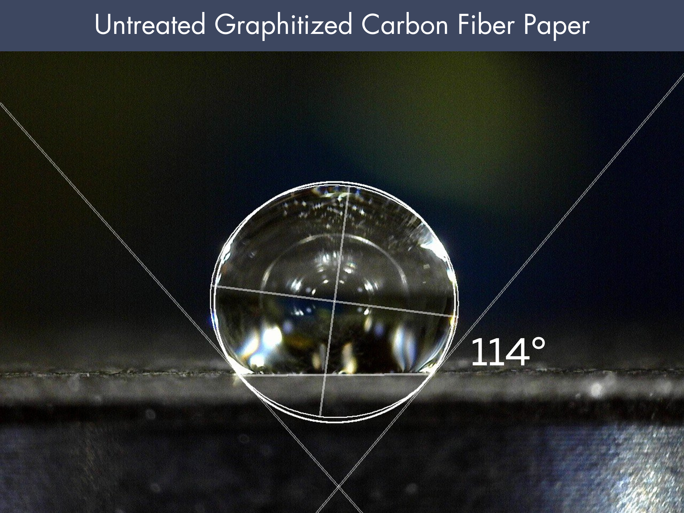
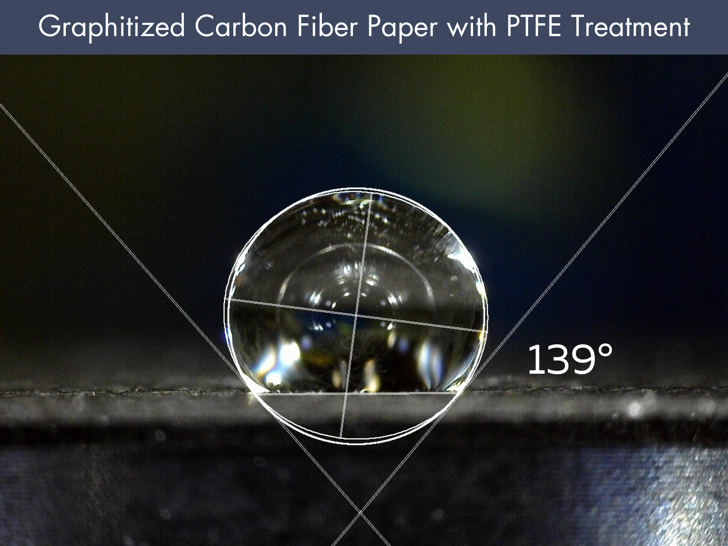
Graphitized carbon paper and plate after manufacturing is somewhat hydrophobic. Water contact angle of graphitized carbon papers that are untreated are usually around 100 °. For some applications, like in fuel cells, more hydrophobic character is needed as water management is critical for fuel cell stacks. For this reason, a hydrophobic, polymer coating is applied to the graphitized carbon fiber product.
Comparison of the water contact angle on graphitized carbon paper before and after hydrophobic PTFE treatment.
The untreated carbon paper (left) has a contact angle of 114°, indicating moderate hydrophobicity. After PTFE treatment (right), the contact angle increases to 139°, enhancing water repellency. This improvement helps prevent water accumulation in fuel cells and electrochemical applications, optimizing gas diffusion and overall performance.
Microporous Layers in Graphitized Carbon Fiber Papers and Panels
The polymer coating on carbon paper and panels makes them more hydrophobic, which helps with water management. However, this comes at a cost. It reduces both porosity and electrical conductivity:
❌ The polymer coating fills some of the pores in the carbon paper or panel, which reduces the overall porosity.
❌ At the same time, most polymer coatings are electrically insulating. When the coating covers the carbon fibers, it disrupts the conductive pathways, increasing electrical resistance and lowering the overall conductivity of the material.
To balance this, a thin microporous layer (MPL) is added on top of the hydrophobic coating. The MPL is made of carbon powder mixed with a polymer and has very small pores, typically around 100 nm in size (ranging from 50 nm to a few micrometers). Because of its small pores and hydrophobic nature, the MPL prevents liquid water from clogging the material, which is especially useful in fuel cell stacks. Additionally, the carbon in the MPL improves electrical conductivity and lowers contact resistance between the gas diffusion layer (GDL) and the catalyst layer. This helps manage water buildup without negatively affecting the GDL’s conductivity.
Bare Graphitized Carbon Fiber Paper
It has a textured, fibrous surface with a metallic gray appearance, showing a visible fiber pattern. The surface looks slightly rough and uneven, indicating its raw carbon fiber structure.
Graphitized Carbon Fiber Paper with Microporous Layer
This paper has a smooth, matte black surface. The microporous layer gives it a dense, coated look, reducing the visibility of underlying fibers.
LINQCELL Graphitized Carbon Fiber Papers with MPL and PTFE Treatment
| Product |
Thickness [mm] |
Basis weight [g/m²] |
Additional Notes |
| GDP120 |
0.12 |
80 |
Available in sheet form only |
| GDP210 |
0.21 |
50 |
Available in sheet and roll form, can come with optional 10 wt% PTFE coating |
| GDP210-MP |
0.21 |
85 |
Available in sheet form only |
| GDP210-MPS |
0.21 |
85 |
Available in sheet form only, produced at 2000°C |
| GDP240 |
0.24 |
90 |
Available in sheet and roll form |
| GDP250 |
0.25 |
65 |
Available in sheet and roll form, can come with optional 10 wt% PTFE coating |
| GDP310 |
0.310 |
80 |
Available in sheet and roll form, can come with optional 10 wt% PTFE coating |
| GDP340 |
0.34 |
125 |
Available in sheet and roll form |
Note: The standard width of a roll of graphitized carbon fiber paper with MPL and PTFE coating is 40 cm.
Is it possible to coat thick (thickness > 340 um) with MPL and PTFE coating?
Yes, it is possible, though more challenging and cost-intensive compared to thinner materials. While roll-to-roll processing is typically more efficient for thinner sheets (<340 µm), we have successfully coated thicker materials as well. Although less commonly requested, CAPLINQ has experience with this and continues to optimize the process for improved efficiency.
What does Graphitization do?
Graphitization is a heat treatment of carbon-based materials typically above 1000 °C under controlled conditions. It is similar to carbonization, but carbonization occurs at lower temperatures, between 600 °C and 1000 °C. During carbonization, volatile materials like water, gases, and light organic compounds are removed from carbon fiber papers and panels, resulting in a carbon-rich material. After carbonization, the carbon fiber paper generally retains its original structure and properties.
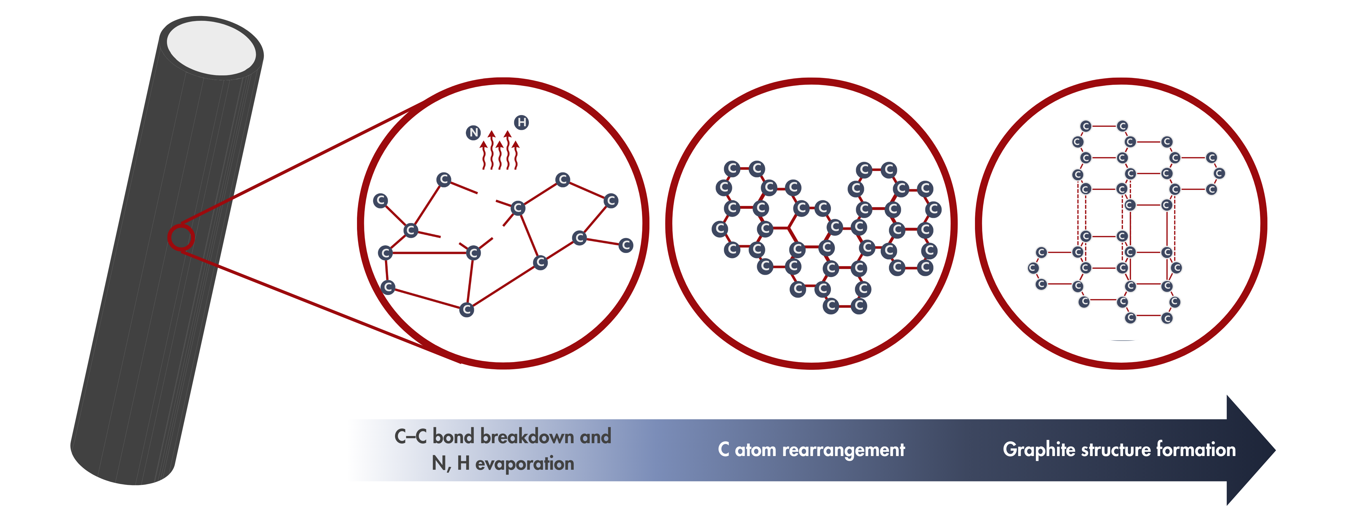
The story is different during graphitization. In addition to being carbon-rich, the material undergoes structural changes as the high temperature provides the energy needed for the carbon atoms to rearrange into a more ordered, crystalline structure similar to that of graphite. This transformation enhances the material properties, such as electrical conductivity, mechanical properties, and thermal stability.
Structural Changes after Graphitization
✅ Increased Crystallinity
Carbon atoms form a hexagonal structure.
✅ Graphite-like Structure
Parallel stacking of hexagonal carbon rings, resembling graphite.
✅ Higher Carbon Purity
Loss of N, H, and other volatiles
✅ Defect Reduction
Fewer disordered or amorphous regions as sp² bonding increases.
What happens at increasing graphitization temperatures?
Our LINQCELLTM graphitized carbon fiber papers and panels have been graphitized at 1600 and 2000 °C. As a general rule of thumb, higher graphitization temperatures yield higher degree of graphitization. In other words, carbon-based material becomes more graphite-like with increasing graphitization temperature. From this, materials graphitized at higher temperatures are expected to exhibit more (improved) graphite-like properties. That is, at increasing graphitization temperatures, higher Young’s modulus (lower compressibility), higher electrical and thermal conductivities, and better chemical stabilities are to be expected.
| Higher degree of graphitization |
As the graphitization temperature increases, carbon atoms move more freely, creating a more ordered, graphitic structure. This improves the material's graphitization level, resulting in enhanced performance and better efficiency in various applications. |
Lower compressibility |
Higher graphitization temperatures also increase the Young’s modulus of carbon materials, making them stiffer and more resistant to deformation. A sheet graphitized at a higher temperature will be less compressible than one treated at a lower temperature, assuming the same porosity. |
| Higher electrical and thermal conductivity |
As the graphitization temperature increases, both electrical and thermal conductivity of carbon materials improve. Higher graphitization temperatures align carbon layers, allowing electrons to move more freely, improving electrical conductivity. The more ordered structure also allows heat to travel more efficiently, significantly improving thermal conductivity. |
Improved chemical stability |
As the graphitization temperature increases, the chemical stability of carbon materials also improves. Higher temperatures promote a more ordered structure, enhancing resistance to oxidation by making the carbon layers more tightly bonded. This reduces reactivity, as the material becomes less likely to interact with external chemicals. Additionally, thermal behavior stabilizes, |
Cost Drivers for LINQCELL Graphitized Carbon Fiber Papers and Panels
Graphitization enhances the electrical, thermal, mechanical, and electrochemical properties of carbon fiber products, but it comes with a hefty price tag. Furnaces running at 2000 °C for hours are as expensive and energy-intensive as it sounds. Optimizing carbon paper production schedules can procure both financial and environmental benefits.
Strategies to Improve Production Costs of Graphitized Carbon Fiber Papers
Optimize Furnace Runs
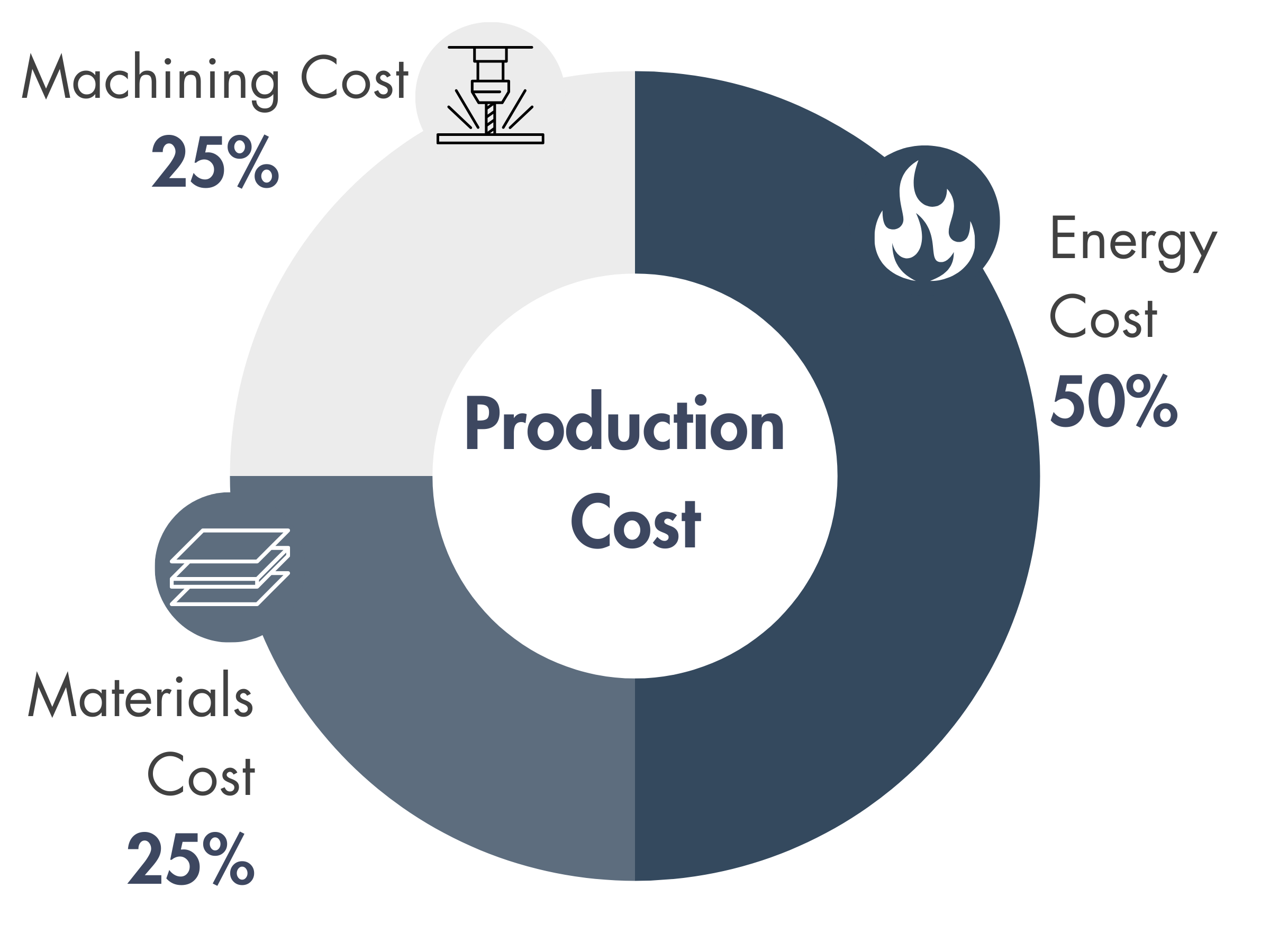
Furnace runs are expensive, contributing to over 50% of operating costs. Running full furnace loads (instead of small batches) minimizes cost per sheet.
Reduce Machining Costs
Using maximum sheet sizes directly from the furnace can cut costs by up to 25%. Relaxing dimensional tolerances reduces material waste and improves yield.
Optimize Material Usage & Sizing
Avoid cutting odd shapes; sheets are rectangular by default. Designing around furnace dimensions (50 cm× 50 cm) maximizes efficiency. Minimizing unnecessary cutting lowers costs and reduces environmental impact.
Read more about the cost drivers and reduction strategies of graphitized carbon fiber papers and panels.
Testing Methods for Graphitized Carbon Fiber Papers and Panels
Thickness Measurement
Thickness of Graphitized Carbon Fiber Paper and Panels/Plates refers to the physical measurement of the material's depth or height, typically measured in millimeters (mm) or micrometers (µm). This thickness is important in different applications, especially in electrochemical devices like fuel cells, water electrolyzers, and other energy storage systems.
-
Graphitized Carbon Fiber Paper: It typically ranges from 100 µm to 500 µm, depending on the specific use case. These thin papers are often used as gas diffusion layers (GDLs) in fuel cells. The thickness of the paper affects the transport properties, such as gas diffusion and conductivity.
-
Graphitized Carbon Fiber Panels/Plates: These can vary more widely, often between 1 mm to several millimeters in thickness, depending on their intended use, structural requirements, and the desired mechanical properties. In water electrolyzers, thicker panels may be used to handle higher mechanical stresses or improve thermal conductivity.
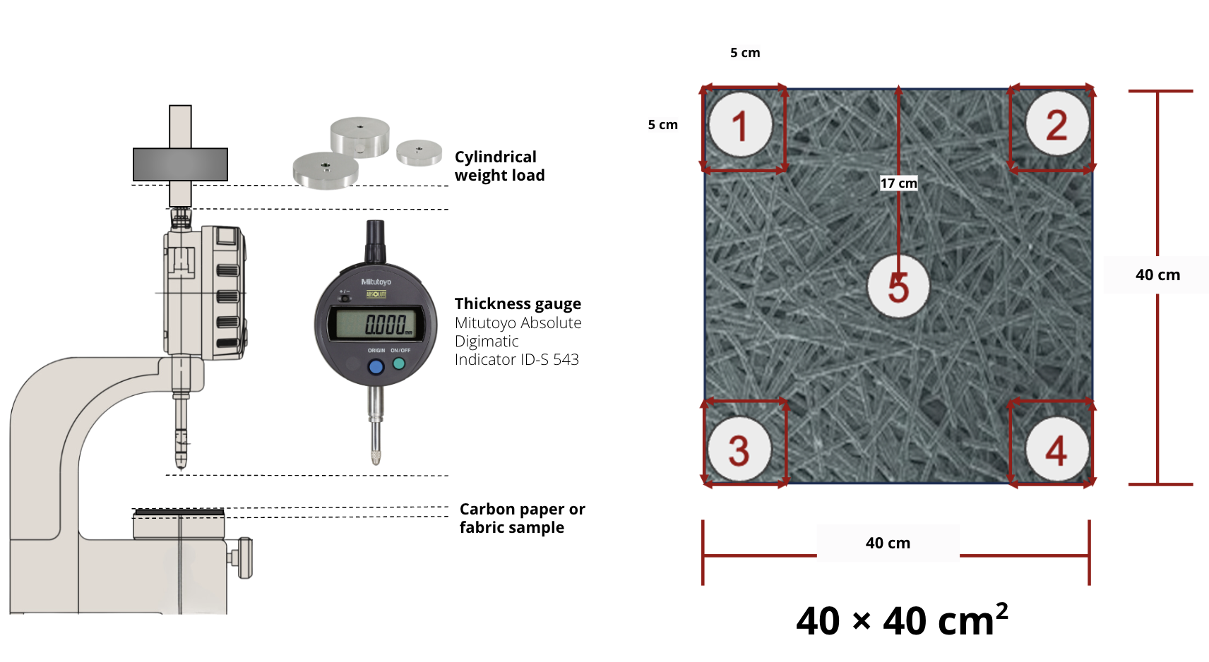 Thickness Gauge:
 Mitutoyo Absolute Digimatic Indicator ID-S 543
Test Standard: ASTM D645 (Standard Test Method for Thickness of Paper and Paperboard)
Weight Load: 50 kPa according to ASTM D645 but can be chosen according to specifications.
Note: The thickness of our products is reported at 50 kPa, per the standard, unless otherwise specified.
Parallelism
Parallelism quantifies the degree at which two or more surfaces on a plate or sheet maintain a consistent distance or are equidistant from each other along a specific reference plane or axis. It is typically expressed as the difference between the thickness of the highest and lowest points on an object or between two surfaces.
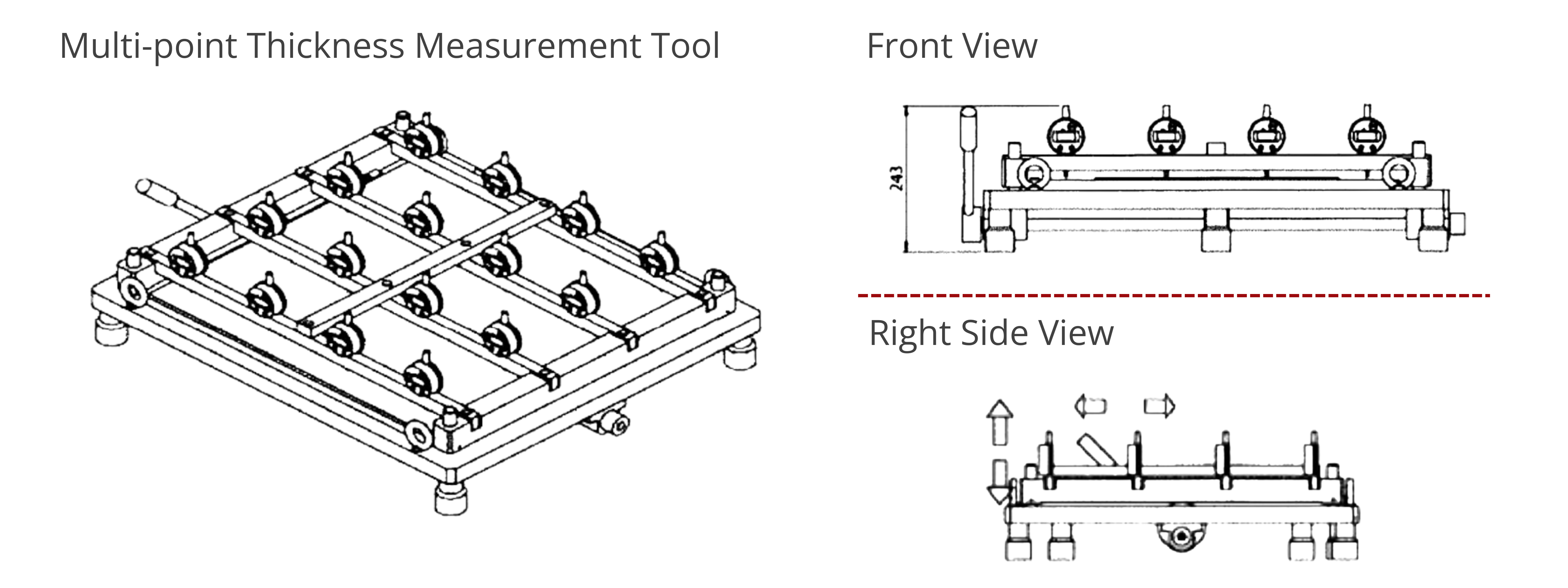
Parallelism Measurement Equipment
- Precision steel base (600 × 600 mm2) and testing parts
- Electronic meter
- Statistical software, 4-pin signal output box, and foot switch
- Working table (maximum load = 1000 kg)
Parallelism Measurement Procedure
- Fix the sample on the flat plate.
- Measure straight by moving either the sample or the height gauges. The number of measurement points will vary depending on the sample dimensions. For example, a 54 × 54 cm2 carbon sheet has 16 measurement points.
- Parallelism is the difference between the highest and lowest measurements. For example, if the thickest point on a plate measures 2.307 µm and the thinnest point measures 2.302 µm, the parallelism is within 0.005 µm. The plate is reported to be parallel within 0.005 µm.
Electrical Resistance Measurement and Resistivity Calculation
The
electrical resistivity of graphitized carbon fiber paper, plates, or panels refers to the material's inherent resistance to the flow of electric current. It is a measure of how strongly the material resists the passage of an electric current and is typically expressed in ohm·centimeters (Ω·cm). It is calculated from the resistance measurement of the material. In the case of graphitized carbon, the resistivity depends on factors like the degree of graphitization, fiber alignment, and material density.
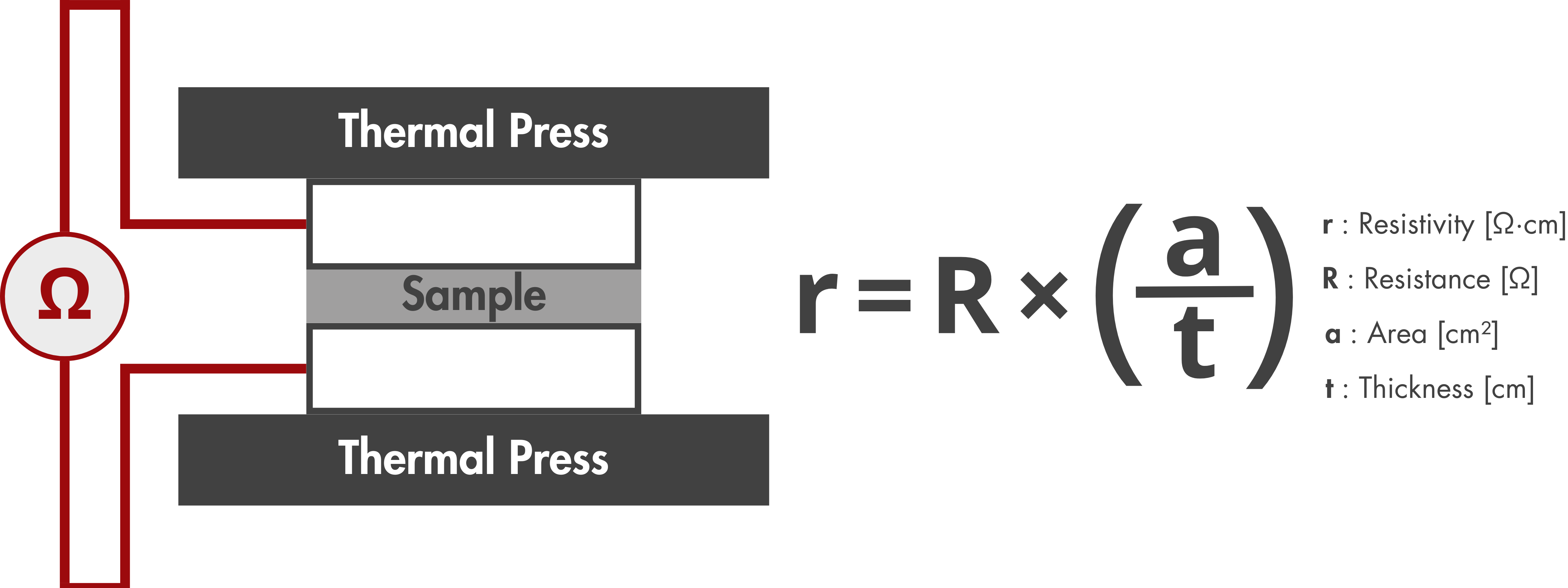
Test Standard: ASTM C611-98
Pressure: 200 psi (14.1 kgf/cm2)
Electrical Resistivity Measurement Procedure
- Prepare a circular sample with a diameter of 5cm.
- Set up the TSURUGA 3566 battery internal resistance AC tester according to the manufacturer's instructions.
- Calibrate the tester to ensure accurate resistance measurements.
- Place the prepared circular testing sample in the heat press.
- Apply pressure to the sample using the hydraulic cylinder (area = 9.7 cm2).
- Using the calibrated TSURUGA 3566 AC tester, measure the resistance (R) of the sample under the specified test conditions.
- Calculate the resistivity of the sample.
Voltage Loss in Graphitized Carbon Fiber Paper, Plates, or Panels
Voltage loss refers to the reduction in electrical potential as the current flows through a material. In the case of graphitized carbon fiber paper, plates, or panels, it is associated with the material's electrical resistivity and resistance to the flow of electric current. The lower the resistivity and resistance, the lower the voltage loss, which means less energy is wasted as heat. For graphitized carbon materials, a lower voltage loss improves performance.
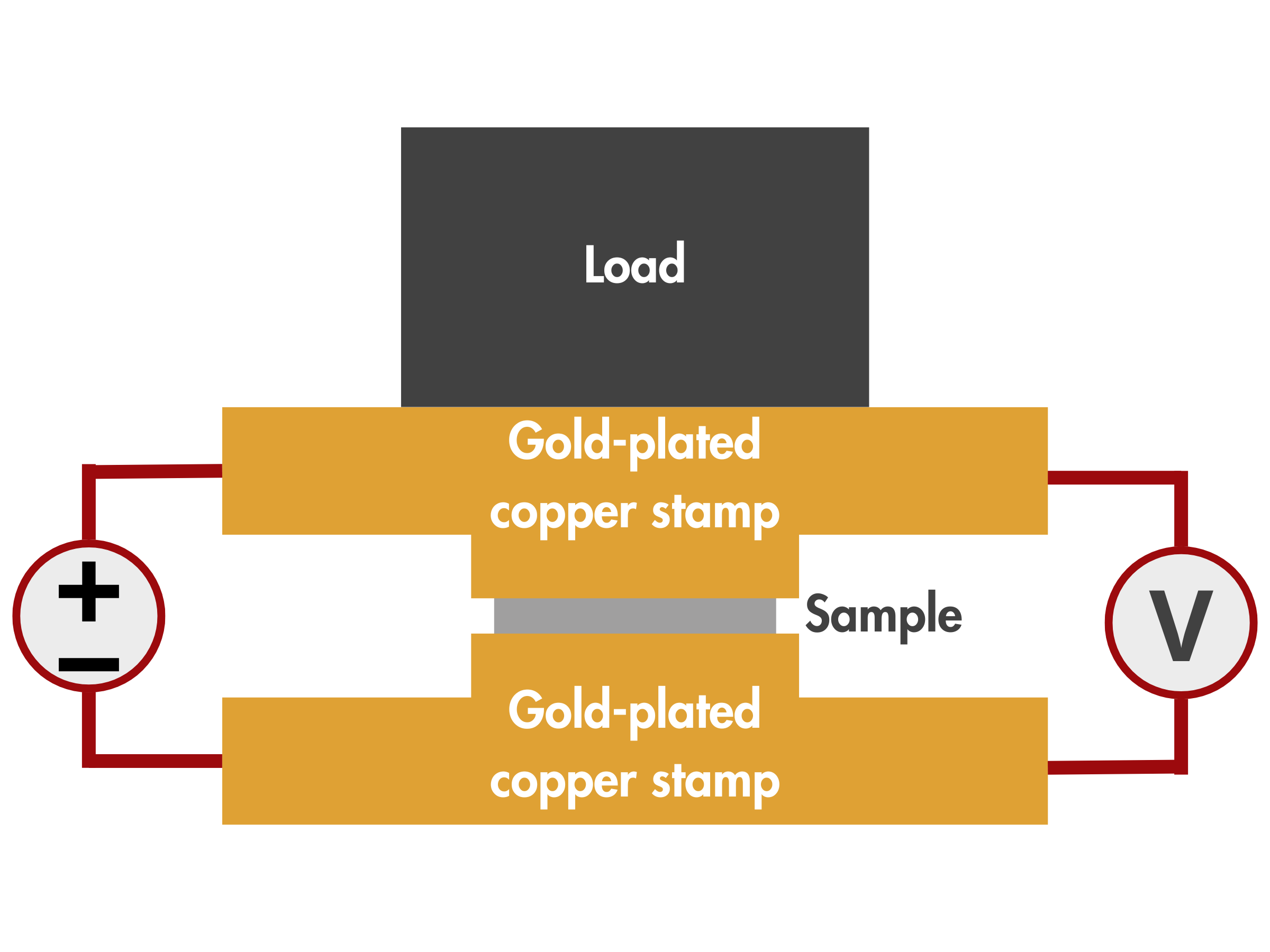
Pressure: 20 N/cm2
Constant current: 500 mA/cm2
Voltage Loss Measurement Procedure
- Ensure that the gold-plated copper stamp and the gold-plated base plate are clean and free from contaminants that could affect electrical contact.
- Set up the voltage measurement instrument (digital multimeter) and connect it to the electrical contact points.
- Position the sample between the gold-plated copper stamp and the gold-plated base plate.
- Apply the pressure and constant current.
- Measure the voltage drop across the contact points using the voltage measurement instrument.
Read more about CAPLINQ's test methods and quality control measures for graphitized carbon fiber paper and panels/plates.
Graphitized Carbon Fiber Papers as Gas Diffusion Layers in Fuel Cells
Thin (thickness < 1 mm) graphitized carbon fiber papers effectively function as both the anode and cathode gas diffusion layers (GDLs) in fuel cells. Gas diffusion layers (GDLs) are key components in fuel cells and electrolyzers, performing several key functions. They ensure efficient diffusion of feed gasses to the catalyst layer, which is essential for continuous electrochemical reactions and electricity generation. The porous structure of GDLs optimizes gas permeability, while their conductive properties facilitate electron transport.
In proton exchange membrane (PEM) fuel cells , the anode GDL enables the diffusion of H2 gas to the catalyst layer, where it undergoes the hydrogen oxidation reaction (HOR), producing H+ ions and electrons. These electrons travel through the external circuit to the cathode, passing through the GDL. At the same time, the cathode GDL allows the diffusion of O2 gas, which reacts with the H+ ions that permeate through the membrane, forming liquid H2O. From this, GDLs not only facilitate gas diffusion but also aid electron transport and assist in water removal to prevent stack swelling.
Functions of Graphitized Carbon Fiber Papers in Fuel Cells
- Hydrogen and Oxygen Delivery: Facilitates the transport of input hydrogen and oxygen gas to the catalyst layer for the electrochemical reaction.
- Electron Conduction: Serves as an electrically conductive pathway, efficiently transferring electrons from the anode to the external circuit.
- Water Management: Assists in removing produced water while maintaining a balance to prevent membrane dehydration or flooding.
- Heat Dissipation: Aids in thermal management by transferring excess heat to other components, such as the bipolar plate.
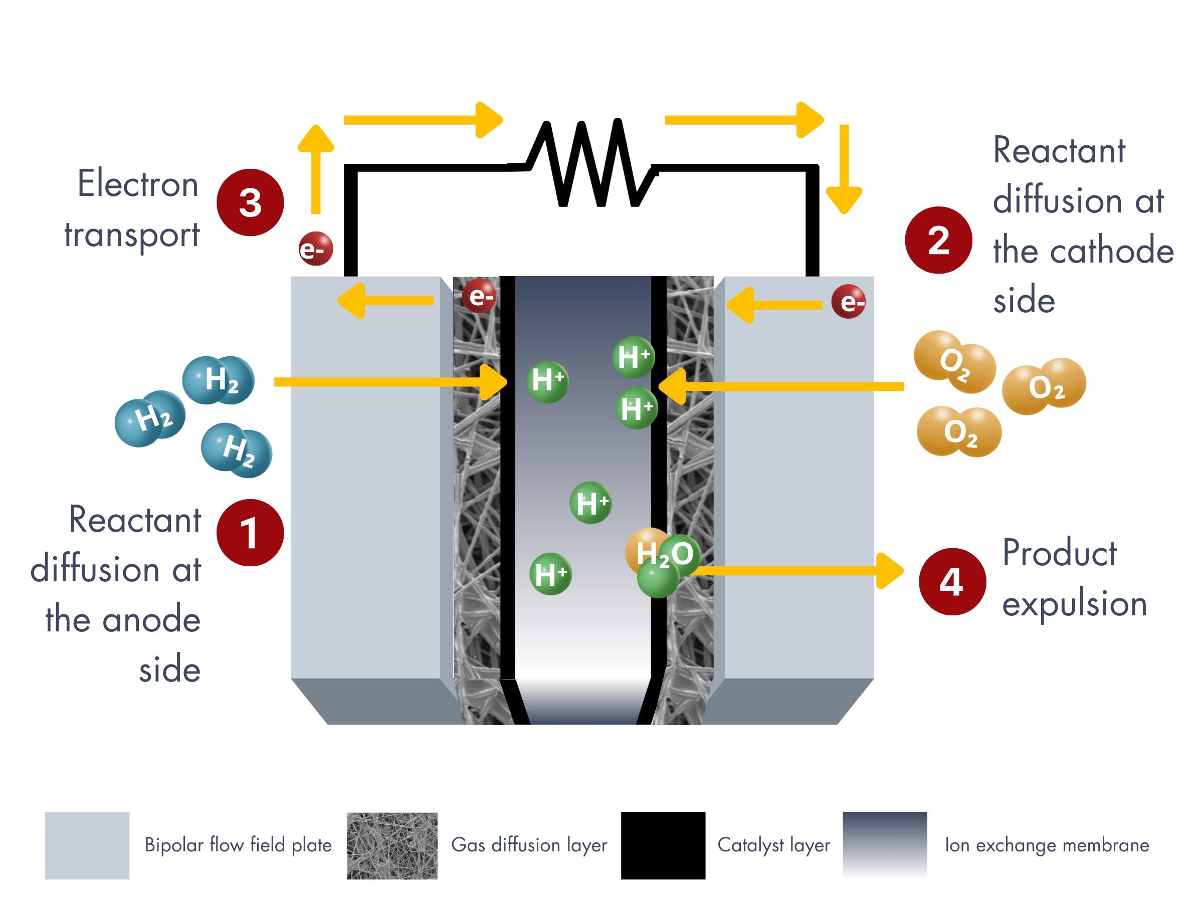
How Graphitized Carbon Papers Meet the Requirements for Gas Diffusion Layers in PEM Fuel Cells
| Function |
Related Properties |
Key Considerations |
Graphitized Carbon Paper Properties |
| Basic Properties |
Thickness, Density/Area Weight, Compressibility |
Thin GDL improves mass and heat transfer and reduces resistance. |
✅ Graphitized carbon papers can be manufactured with optimized thickness and density, ensuring lower resistance and enhanced mass and heat transfer properties. |
| MEA Assembly |
Stiffness/Flexibility, Tensile Strength, Flexural Modulus |
Mechanical strength with appropriate rigidity and flexibility helps the stack withstand expansion due to water absorbency and provides stability under long-term operating conditions. |
✅ Graphitized carbon papers have good mechanical strength, balancing rigidity and flexibility to handle the stresses in fuel cells. The carbonizable resin in them affects porosity, and by optimizing resin content and the carbonization process, we can improve tensile strength and stability over time. |
| Transport Process |
Reactant Gas Transport
Porosity, Pore Size Distribution, Gas Permeability |
Gas permeability is essential for gas transfer.
High porosity increases permeability.
Proper pore size distribution ensures uniform gas distribution on electrode surfaces. |
✅ Graphitized carbon papers typically offer high porosity (>60%) and controlled pore size distribution, promoting effective gas permeability and ensuring uniform gas flow through the electrode. |
Water Transport
Hydrophobicity (Surface Energy/Contact Angle), Pore Size Distribution |
Hydrophobicity prevents excessive moisture from blocking pores and reducing gas permeability.
Achieved by adding PTFE layers and using carbon black or graphite in the MPL. |
✅ Graphitized carbon papers often require additional hydrophobic treatments, such as PTFE coating, to achieve the desired water management. The hydrophobicity helps prevent water from blocking pores and compromising gas permeability. |
Electron Transport
Through-Plane Resistance, Compressibility, Surface Roughness |
Compressive stress reduces GDL thickness, increasing electrical conductivity and permeability. |
✅ Graphitized carbon papers offer excellent electron conductivity due to their high degree of graphitization. |
Heat Transport
Thermal Conductivity |
High thermal conductivity is required for heat dissipation. |
✅ Graphitized carbon papers have good thermal conductivity, aiding in the efficient removal of heat during fuel cell operation, ensuring temperature uniformity and preventing overheating. |
| Stability |
Purity, High Corrosion Resistance, Surface Stability, Heat Resistance |
Ensures long-term durability and performance. |
✅ Graphitized carbon papers exhibit excellent corrosion resistance and surface stability, particularly in acidic environments. |
Read more about the properties of graphitized carbon fiber papers related to their application as gas diffusion layers in fuel cells.
LINQCELLTM Graphitized Carbon Fiber Paper Performance in Fuel Cells
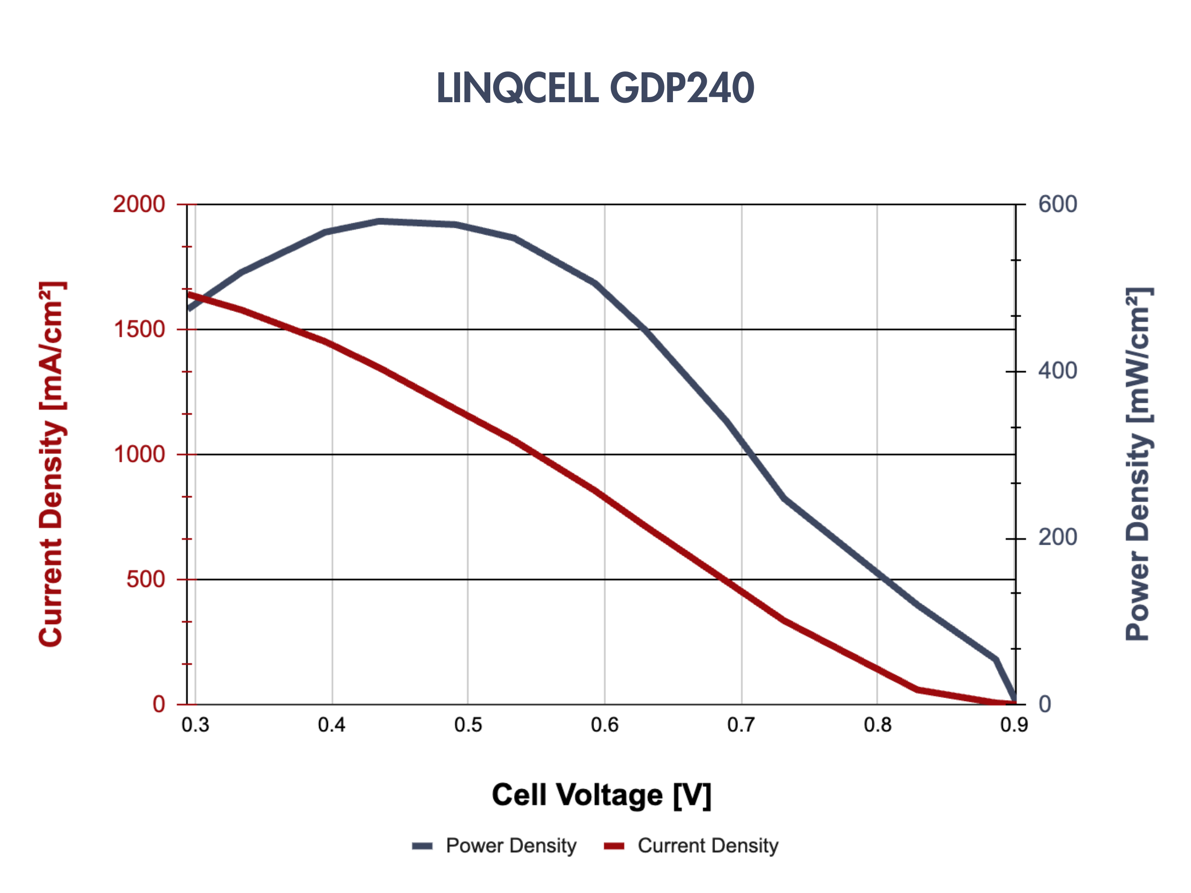
Representative polarization curves for some LINQCELLTM Graphitized Carbon Fiber Paper Products
| Parameter |
Value |
| Reaction Area |
300 cm² |
| Fuel Supply Method |
Constant Flow |
| Relative Humidity |
100% |
| Test Temperature |
60 °C |
| Anode Flow Rate |
1.5 splm (H2) |
| Cathode Flow Rate |
2.5 splm (Air) |
| Operating Pressure |
10 psi |
| Clamping Pressure |
10 psi |
| Parameter |
Value |
| Active Area |
25 cm2 |
| Anode/Cathode Stoichiometric Ratio |
2.5/1.5 |
| Anode Humidification Temperature |
65 °C |
| Cathode Humidification Temperature |
36 °C |
| Cell Temperature |
60 °C |
| Torque |
25 kgf⋅cm |
Graphitized Carbon Fiber Panels as Cathode Porous Transport Layers in Water Electrolyzers
Porous transport layers (PTLs) or liquid/gas diffusion layers are important components in water electrolyzer stacks. s shown in the figure below, PTLs facilitate the delivery of liquid reactants from the flow plate channels to the catalyst layer (①) while also allowing for the efficient removal of gaseous products, oxygen at the anode and hydrogen at the cathode (②). This process creates a countercurrent two-phase flow through the PTL. If the product gasses are not effectively removed from the system, H2 and O2 can clog the pores of the PTL. This blockage not only decreases the availability of liquid reactants for the reaction but also leads to membrane dehydration, which negatively impacts its ionic conductivity.
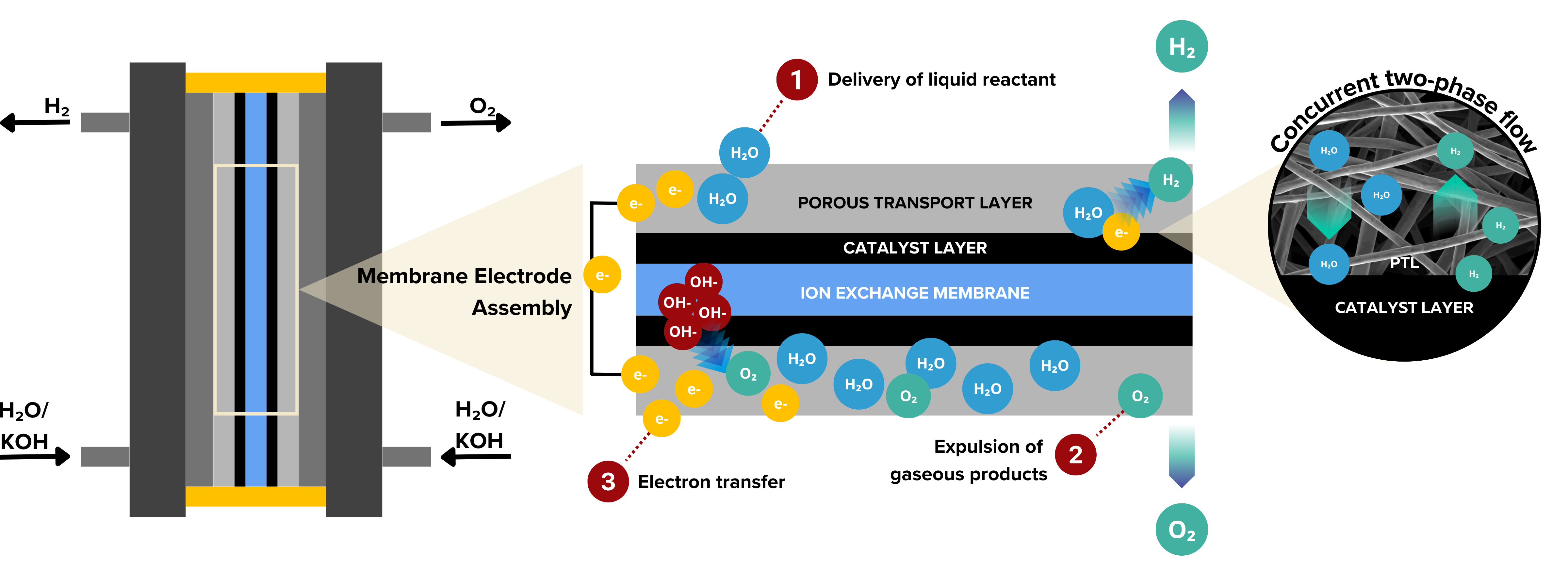
Gas diffusion layers vs. Porous Transport Layers? Gas diffusion layers and porous transport layers are similar terms but with distinct contexts. PTLs is a broader term, commonly used in water electrolyzers, to describe materials that facilitate reactant and product transport. GDLs, on the other hand, are commonly used fuel cells and are designed to manage gas diffusion and electron conduction. While both terms involve mass transport, GDLs are specialized for fuel cells, while PTLs have a more general application.
As mentioned above, graphitized carbon fiber papers are used at the anode and cathode of fuel cells. Is it the same for graphitized carbon fiber panels or plates in water electrolyzers? No. The placement of the PTL is important because the anode and cathode sides of water electrolyzers operate under different conditions and environments. Each side experiences distinct chemical reactions that do not only affect the performance but also the stability of the PTL.
At which side of water electrolyzers are graphitized carbon fiber panels used?
As mentioned above, graphitized carbon fiber papers are used at the anode and cathode of fuel cells. Is it the same for graphitized carbon fiber panels or plates in water electrolyzers?
The placement of the PTL is important because the anode and cathode sides of water electrolyzers operate under different conditions and environments. Each side experiences distinct chemical reactions that do not only affect the performance but also the stability of the PTL.
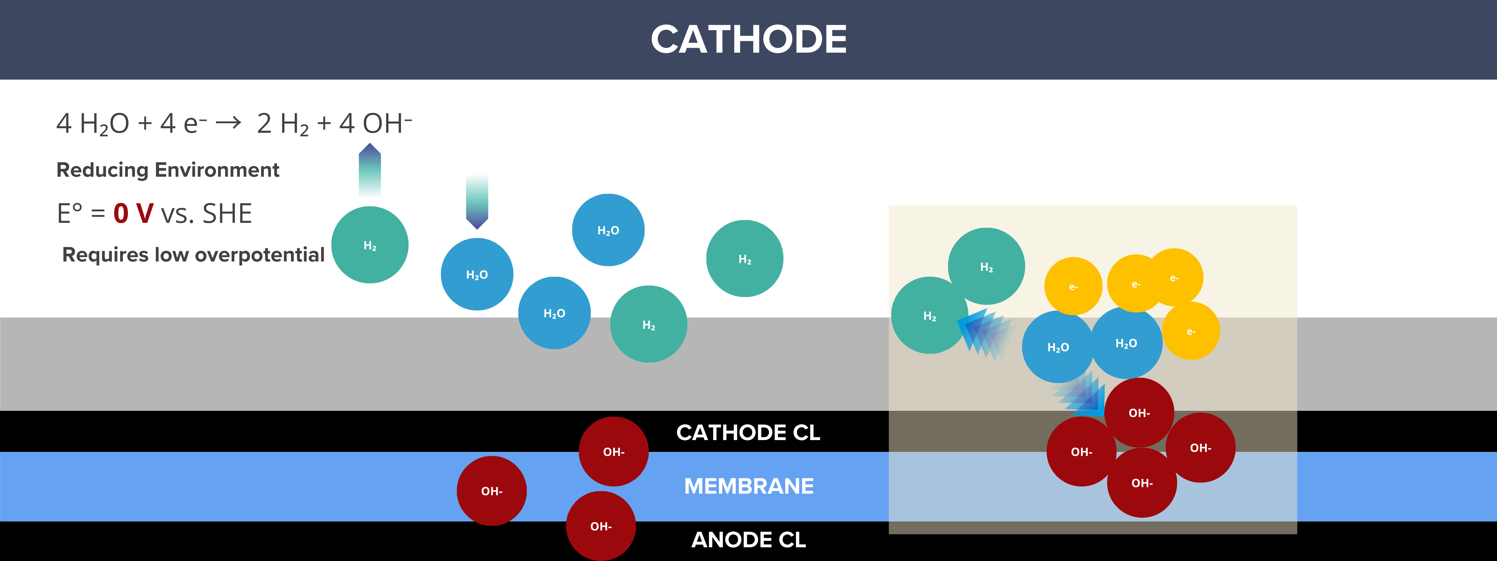
By convention, the cathode is the site where reduction reactions occur, and in water electrolyzers, this is where the hydrogen evolution reaction (HER) takes place, generating H₂ gas. As a result, the cathode side operates under a reducing environment, which minimizes the likelihood of oxidation reactions. Materials on the cathode side are less prone to corrosion because they are not exposed to harsh oxidative conditions. Since oxidation is not a major concern, carbon materials are considered as the benchmark PTL for the cathode side.
Key Features and Benefits of LINQCELLTM Graphitized Carbon Fiber Panels as Cathode PTLs of Water Electrolyzers
✅ Low resistance, which minimizes energy losses and improves overall fuel cell efficiency
✅ Customizable GDL solutions to meet specific performance needs
✅ High corrosion resistance, making them durable in acidic conditions of fuel cells
✅ High mechanical strength, critical for maintaining integrity under high-pressure conditions
✅ Customizable compressibility
Customizable Compressibility of LINQCELLTM Graphitized Carbon Fiber Panels for Water Electrolyzers
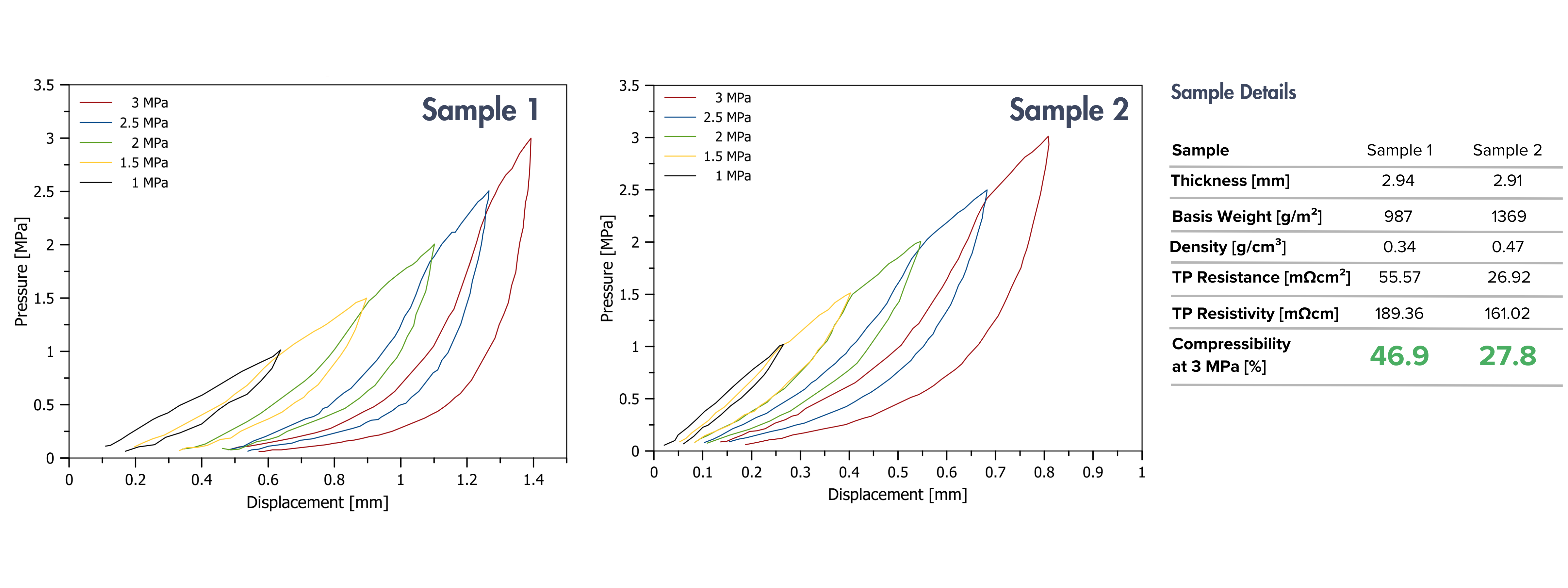
CAPLINQ can fine-tune compressibility to achieve the perfect balance of electrical conductivity, gas permeability, and mechanical strength.
Presentations
LINQCELL Graphitized Carbon Fiber Paper and Panel Production Process Control
Rose Anne Acedera, 2023
This presentation provides an overview of the production process control for LINQCELL Graphitized Carbon Fiber Paper and Plate, highlighting key parameters, quality control measures, and process optimizations.
LINQCELL Porous Transport and Gas Diffusion Layers for Water Electrolyzers and Fuel Cells
Rose Anne Acedera, July 2024
This presentation showcases CAPLINQ's offerings for porous transport layers in electrolyzers and gas diffusion layers in fuel cells, including graphitized carbon fiber papers and plates, as well as metal PTLs such as titanium, nickel, and stainless steel.
Cost Drivers for the Manufacturing of LINQCELL GDL
Rose Anne Acedera, 2024
This presentation will cover the key cost drivers in manufacturing LINQCELL GDL, including raw materials, processing techniques, energy costs, and quality control. It will also highlight how these factors impact overall cost efficiency and product performance.
Related Blogs

CAPLINQ Develops Sustainable PFAS-free, Hydrophobic Coatings for Carbon Gas Diffusion Layers
Rose Anne Acedera, February 2025
This blog discusses CAPLINQ’s development of sustainable, PFAS-free hydrophobic coatings for carbon gas diffusion layers (GDLs).

What are the Differences between Carbon Cloth, Paper, and Felt?
Rose Anne Acedera, January 2025
This blog explores the key differences between carbon cloth, paper, and felt, focusing on the differences between their manufacturing processes and resulting properties.

Benchmark Porous Transport Layers for Water Electrolyzers
Rose Anne Acedera, January 2025
This blog explores benchmark porous transport layer (PTL) materials, including carbon, titanium, and nickel, for water electrolyzers. It also discusses the role of thick graphitized carbon fiber plates or panels as cathode PTLs, emphasizing their structural stability and performance in PEM and AEM water electrolyzers.