Thermal Gap Pads
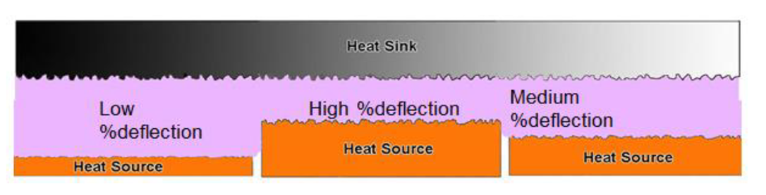
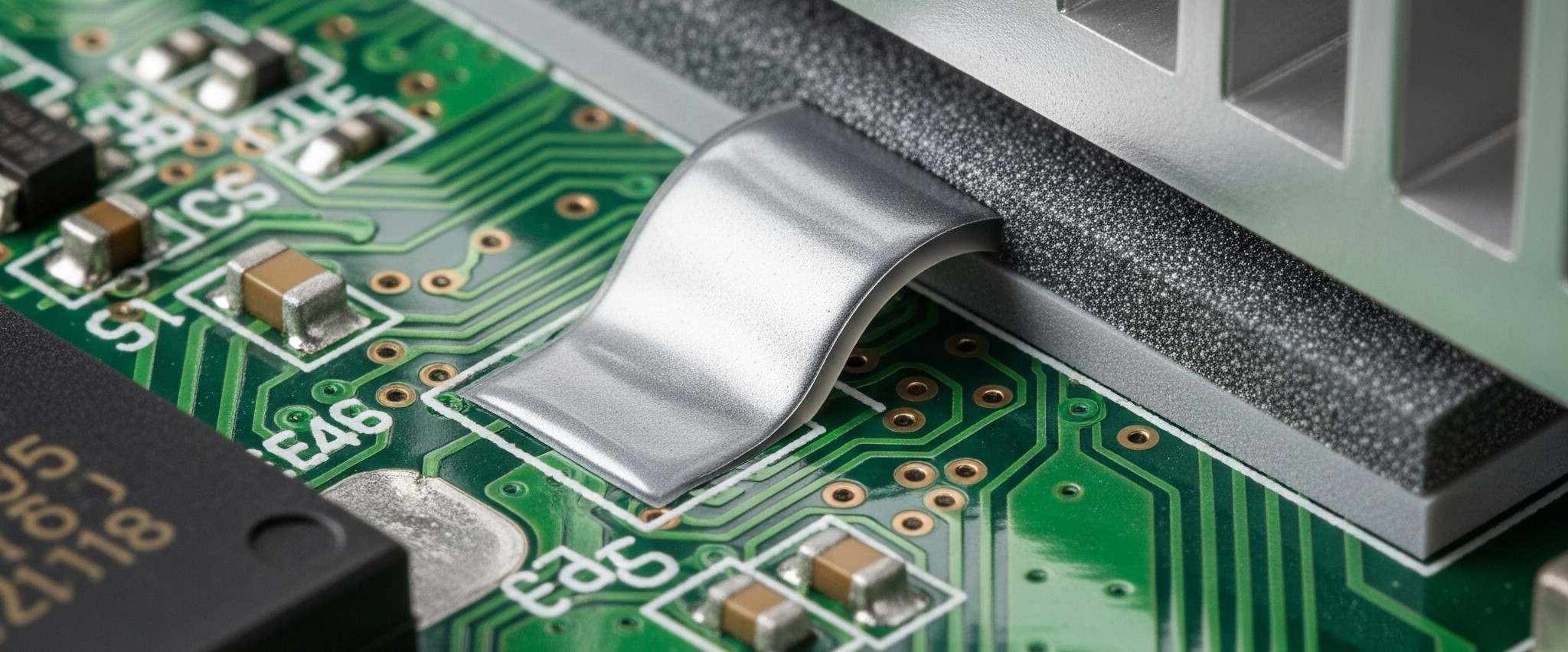
A gap filler material is a type of thermal interface material to fill the gap (>0.5mm), while phase change material and thermal grease are designed for thin bondline thickness (<0.1mm) applications. It is expected to be compliant enough to deflect to accommodate multiple module heights and tolerance variation within applications without generating excessive levels of pressure within the system. Thermal gap pads, thermal putty pads, two-part hybrid gels, and one-part hybrid gels are all considered as gap filler materials.
Key Features Of Gap Filler
)(4).png)
TGPs are Silicone-based
Gap fillers are usually silicone based because silicone a lot of attractive properties such as excellent surface wetting, high thermal stability, flexibility and physiological inertness. The silicone matrix is filled with thermally conductive fillers such as boron nitride, zinc oxide or alumina. These fillers make up the functional portion of the gap filler which give it its thermal properties.
|
Thickness & Thermal Conductivity
Standard thicknesses of gap fillers tend to be 0.25-5mm (10-200 mils). This thickness range allows the gap filler to deform and fill these gaps without exerting excessive pressure that could damage components or reduce mechanical reliability. Most have thermal conductivity ranging from 0.5 to 10 W/mK, which effectively provides a thermally conductive path for heat transfer.
|
Conformaility
Gap fillers are often expected to deflect 10 to 70 % of their initial thickness (compression) without generating excessive pressure and bleeding issues.
|
Convenient Packaging Forms
These materials are usually delivered as die cut parts between release films, on a roll, as sheets or in cartridges for automated dispensing
|
Thermal Gap Pad Selection Guide
Thermal conductivities, boneline thickness and reliability capabilities are the most important considerations for TIM selection. This also works for thermal fillers like thermal gap pads. However, there are some other features need to be considered specifically for gap filler pads:
).png)
Compression
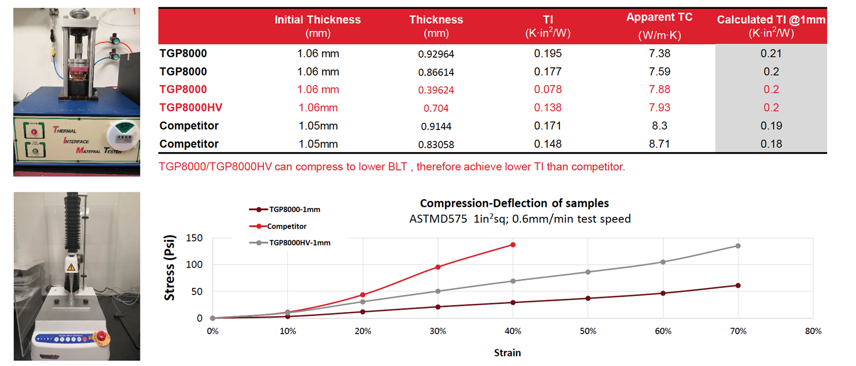
Some compression (at least 10% compression) is required to overcome/decrease the contact thermal resistance. The relationship between deflection and compression is not linear. You could find the Stree-Strain Curve of compression properties on each product page. For example, the figure below shows the TGP8000 and high breakdown volatge version TGP8000HV's compressibility and how TI (thermal impedance) & Thickness change by compression ratio.
Difference between Peak Stress and Residual Stress
In gap compression applications, particularly involving thermal interface materials (TIMs), peak stress and residual stress represent different stages of mechanical behavior during and after compression. Peak stress refers to the maximum stress exerted on the material during the compression process. It occurs at the moment when the TIM is being compressed to bridge the gap between surfaces, and it reflects the material's initial resistance to deformation. A higher peak stress typically indicates a stiffer or thicker material, which may require greater force during assembly.
In contrast, residual stress is the remaining stress in the material after the compressive force has been released. It reflects the material's ability to retain pressure and maintain contact over time, which is critical for long-term thermal performance and mechanical stability. Residual stress provides insight into the elastic recovery or permanent set of the TIM, influencing how well it continues to conform to surface irregularities and maintain thermal conductivity throughout its service life.
Thickness Tolerance
When starting the design process, identify the nominal gap and know the tolerances. The thickness range of thermal gap pads we provide is 0.5-5.0mm with 0.25mm incremental. Thickness Tolerance: ±10% while thickness>1mm; ±0.1mm while thickness is 0.5-1mm
Hardness
Ideally, the softer the gap filler material, the better, since high assembly pressure may cause gap bleeding out and components deformation. However, materials that have a higher thermal conductivity and more curing extent, the harder it gets due to the high filler content. It is harder for high TC product to own elasticity and bounce back while pressure is moved away.
Additional Layer
Some reinforcement carriers might be added on normal gap pads to enhance specific properties as customers need. Some common ones are:
- Woven Fiberglass (no PSA) to provide reinforcement against tearing down and a clean low tack interface surface
- Polyimide Film Or PEM Film to offer an excellent dielectric strength and permit gap pad to see a shearing motion
- Aluminum Foil (with PSA) to allow a pressure sensitive adhesive on the gap pad
Minimize Thermal Pad Bleeding
|
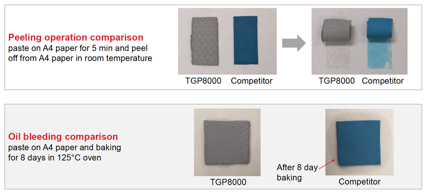
The biggest issue we face with silicone pads is bleeding. Surprisingly enough there are no set test methods to control bleeding of Thermal gap pads. As a general rule of thumb there's NO thermal gap pad in the industry right now that doesn't bleed. Silicone pads can and will bleed given the right circumstances, regardless of manufacturer. That doesn't mean that Silicone free pads are not prone to it. Silicone free pads will also bleed. They will just not bleed Silicone.
Bleeding is different than outgassing. It concerns longer molecular chains and it depends on a variety of parameters. Bleeding depends on the pressure differential on the pad, how much free (not cross linked) silicone remains and the molecular weight (length) of the remaining unlinked chains.
|
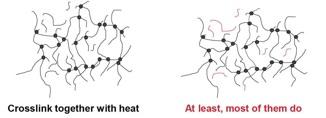
In this case, pressure plays a much bigger role than heat and orientation. Compared with competitors, we minimize bleeding largely. Check the comparison of bleeding results below:
|
Enhance Thermal Gap Pad Breakdown Voltage
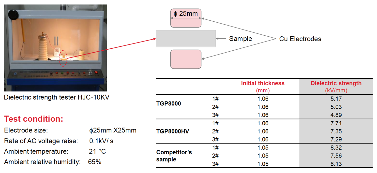
While bleeding tests are not standardized, Dielectric strength testing is quite straightforward. The sample is placed between two 25 x 25mm Copper electrodes in ambient temperature and 65% ambient relative humidity while the voltage is raised by 0.1kV/s until the AC current crosses through. Optically, this cross through is usually in a form of a pinch/hole in the material, sometimes invisible to the bare eye. Tests are being conducted in a Dielectric strength tester - HJC-10KV at the time of writing of this content.
Honeywell's TGP8000HV has the lowest Thermal impedance out of all the entire thermal gap pad portfolio, plus higher breakdown voltage than the plain TGP8000 version. Check the dielectric strength data of TGP8000HV below.
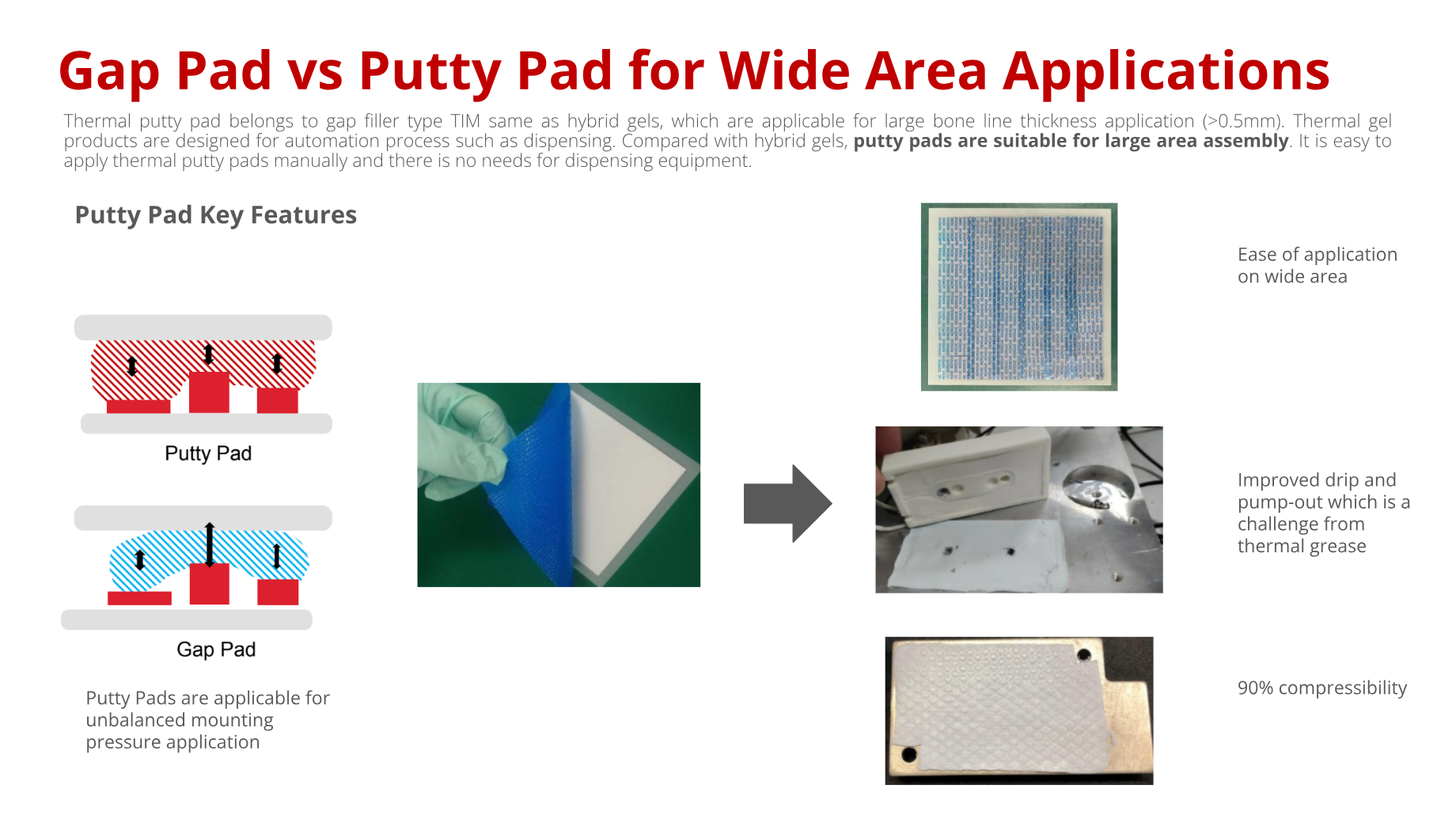
Thermal Gap Pads vs. Thermal Putty Pads
Compatibility of Putty Pads and Gap Pads with Immersion Cooling Fluids
Immersion cooling has been gaining significant attention as a thermal management strategy, especially for high-performance electronics and data centers. A common question we receive is whether thermal interface materials (TIMs), particularly putty pads and gap pads, are compatible with dielectric immersion fluids such as polyalphaolefin (PAO)-based fluids.
Putty Pads and PAO Compatibility
From our experience and testing, putty pads are not recommended for use in PAO-based immersion cooling systems. PAO fluids belong to the class of carbon-based dielectric liquids. Both silicone-based and silicone-free gap fillers tend to swell in PAO fluids, with the extent of swelling depending largely on the material’s crosslink density.
Putty pads are typically formulated with a lower degree of crosslinking, which makes them especially vulnerable. In fact, when fully immersed in PAO fluids, putty pads can fail in as little as two days of continuous exposure. While survival times are longer when the material is compressed between a heatsink and electronic components (since the pad is not fully exposed to the fluid), their use is still not recommended for immersion cooling applications due to long-term reliability risks.
Thermal Gap Pad as an Alternative
In immersion cooling systems, low-thermal-conductivity (1–2 W/m·K) gap pads are often not an option, as fluid circulation itself provides effective heat removal. Instead, higher thermal conductivity gap pads in the 3–5 W/m·K range are widely adopted, especially in markets such as China.
For these applications, our TGP3000 to TGP5000 series gap pads are a better choice. These materials are engineered with a higher crosslink ratio in their formulation, which improves their stability and compatibility in immersion environments compared to putty pads.
For critical components such as main processors or high-power chips, customized solutions like Indium metal pads can also be considered, offering excellent performance in direct liquid-contact cooling scenarios
Related Blogs

Phase change materials 101
George Kountardas, February 2023
This blog discusses the fundamentals of phase change materials.

Si vs Si-Free TIMs
Darlene Pudolin, August 2023
This blog discusses the differences between thermal interface materials with and without silicones.

TIM Thermal Conductivity
Darlene Pudolin, March 2024
This blog explores how thermal conductivity of thermal interface materials can be improved.